Balancing non-inverting opamp gain to minimize distortion
-
The Experiment
Here is a common dual opamp configuration:
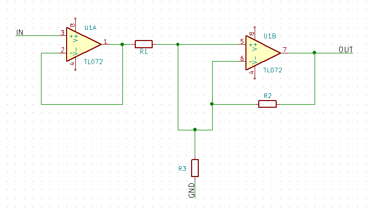
U1A is an attenuator configuration while U1B is a positive gain configuration. Here R3 is just a resistor to ground, but in practice R3 might represent a sub-circuit consisting of an active filter.
What is the relationship between the two opamps regarding their gain and distortion levels?- ##### Gain Calculations
The formula for U1A gain is a simple voltage divider:
The formula for U1B gain is the standard non-inverting gain formula ${\large \frac{R2}{R3} } + 1 $
For example, take the following resistor values:
Then the gain of the individual opamps can be caluclated:
The final output gain of the series opamps can be found with the product of the U1A attenuation and U1B gain factors:
-
The Results
Assuming that series resistor R1 and feedback resistor R2 are equal then the final gain - the product of U1A and U1B gain - will always equal unity:
| R1 | R3 | U1A Gain | R2 | R3 | U1B Gain | Output Gain |
|---|---|---|---|---|---|---|
| 2700 | 1000 | 0.27 | 2700 | 1000 | 3.70 | 1 |
| 2700 | 4700 | 0.64 | 2700 | 4700 | 1.57 | 1 |
| 2700 | 10000 | 0.79 | 2700 | 10000 | 1.27 | 1 |
| 2700 | 47000 | 0.95 | 2700 | 47000 | 1.06 | 1 |
| 2700 | 100000 | 0.97 | 2700 | 100000 | 1.03 | 1 |
-
The Conclusion
Note that a lower value of R3 will increase signal attenuation in U1A which will in turn require a higher gain in U1B to compensate.
Higher gain will cause higher distortion in the form of increased noise floor. Therefore, care should be taken to choose a suitably high value of R3 so that distortion requirements can be met.