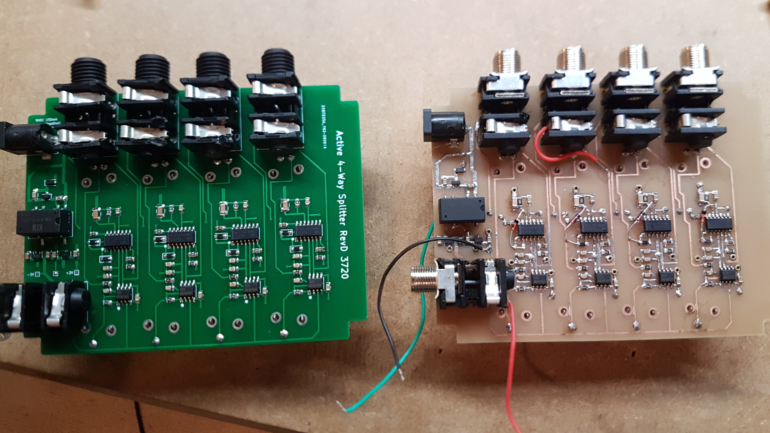
Hybrid splitter and mixer guitar pedals using analog audio signal path with DSP-controlled peak detection
random things I made and things I learnt making them
Category: Electronic Design
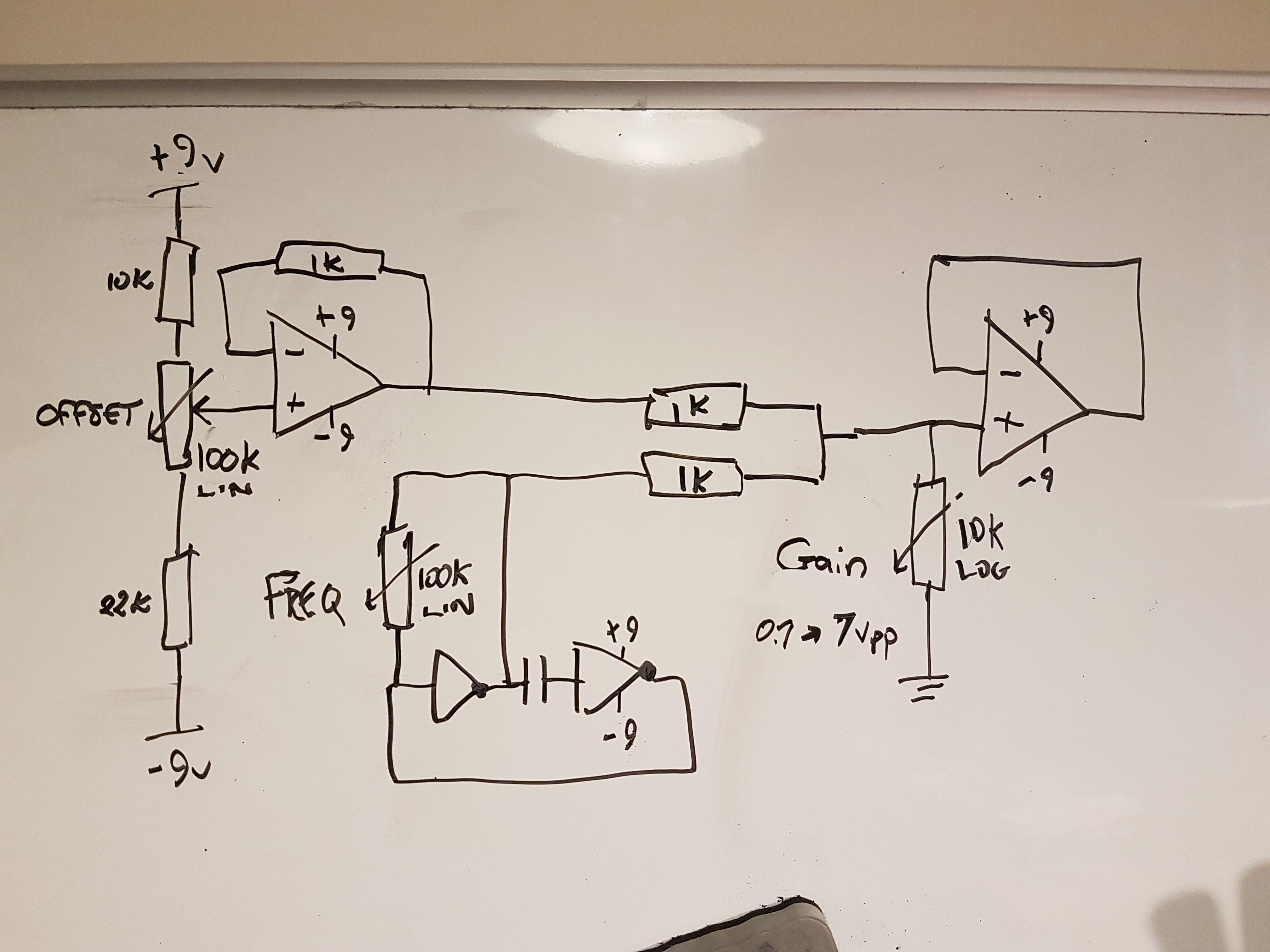
A series of analog waveform generator designs
Each of these designs use a TC4667 charge pump to create a negative voltage from a +9VDC supply. DC offset adjustment of the AC output signal is attained via the +/- voltage divider OFFSET potentiometer. This is summed along with the generated waveform. The amplitude of the output waveform is determined by the feedback network on the non-inverting leg of the last op amp, controlled by the GAIN potentiometer. You can use a dual supply with the hex inverter IC to attain offset above/below ground.
Balancing non-inverting opamp gain to minimize distortion
Relationship between opamps gain and distortion.
555 Timer cheatsheet
Here’s is a quick visual guide to illustrate how the trigger and threshold pins can affect the output of this timer IC chip. Trigger active Here the signal sent to the trigger is less than 1/3 of the supply voltage (VCC). The output is 1. The discharge transistor is disabled. Threshold active Here the signal…
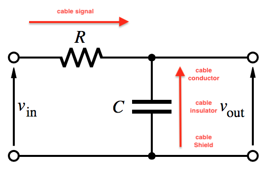
Why don’t you get “tone suck” from a long speaker cable?
The source impedance from your instrument/amplifier signal, coupled with the capacitance
of the cable, creates a low pass filter.
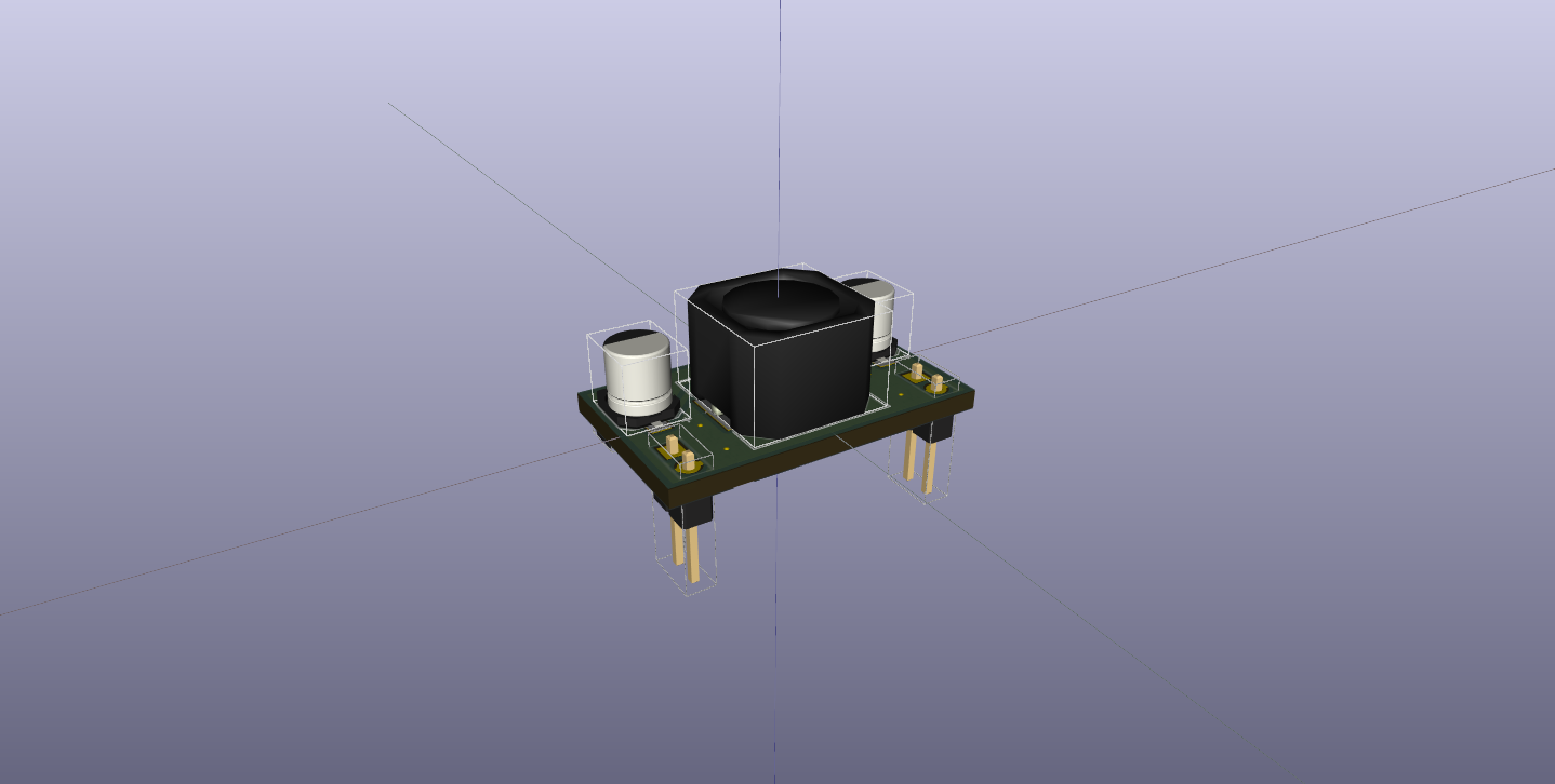
Not another MC34063 switch mode power supply….?!
This design uses the “classic” MC34063 switching regulator IC to invert the input voltage rail to a negative voltage, simultaneously stepping up/down the output depending on the position of the rotary dip switch. The resistors in this design are set for -3.3v, -5V, -9V and -15V.
AC Theory Cheatsheet
Inductance is the relationship between the current and the magnetic field generated in a coil. Each is proportional to the delta of the other. [latex] {\large \frac{L = ( d^2 n^2)}{l + 0.45d} } [/latex] [latex]d2[/latex] is diameter of coil in meters [latex]n[/latex] is number of coil turns [latex]I[/latex] is length of coil in meters…


