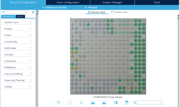
The STM32CubeIDE can be used to generate device tree source file (.dts) for your embedded linux image. These describe the hardware for the board on which linux will run. This is compiled into a device tree binary file (.dtb) which is included on the image and loaded by u-boot along with the Linux kernel zImage.
For those familiar with STM32 CortexM development, STM32CubeIDE is the same pinmux code generation tool. It generates a device tree with “comment sections” that need to be filled out by the user. The simplest option is to create a STM32MP1-DK (development kit) project and copy the required comment sections over to your own dts file. See the forum page for workshop slides that go into more detail about these comment sections
In this article we are going to create two STM32CubeIDE projects – a DK-2 project with all the presets and a custom project for the custom board – and compare them side-by-side.
A. Device Configuration Tool
DDR
This assumes you are using the same MT41K256M16TW-107 DDR chip used on the DK2.
Here are the DDR settings from the DK2:
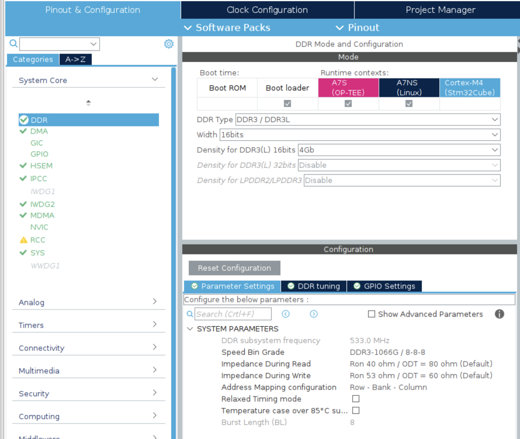
Note you can only change the DDR Subsystem Frequency in the Clock Configuration tab. If you are prompted to auto resolve clock issues, press yes. In this case it resolves the errors but it sets the DDR clock too low. Manually set the speed to 533 and press enter to see if the wizard can resolve it. Right click the textboxes to lock the values to prevent unwanted changes later on.

DMA
The DK2 board has both DMA set to the processor. This might not be the final configuration you want but for now lets use it.

GIC
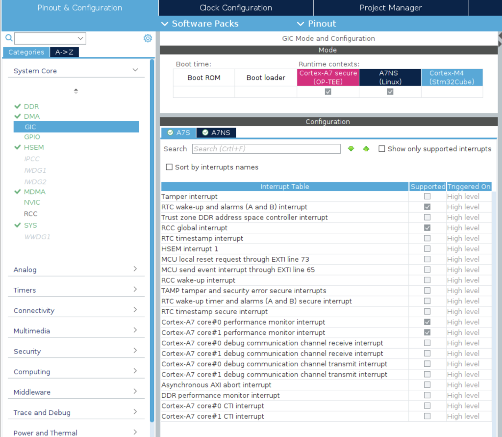
Since the DK2 comes with many onboard interfaces, a lot of periperhals and interrupts are enabled. By default our custom configuration will not have these peripherals enabled. So the interrupts list will be much shorter. This is fine. We just need to make sure we enable the core system interrupts.
The most important interrupts at this point:
- RTC Wakeup and alarms (A and B) interrupt
- RCC global interrupt
- Cortex-A7 core 0 performance monitor interrupt
- Cortex-A7 core 1 performance monitor interrupt
Make sure these are set for both A7S and A7NS:
GPIO
This is where the individual MPU pins are enabled for each peripheral. We should only see the DDR pins in the list because we enabled the DDR peripheral in the previous steps…but not much else. As a bare minimum, we will need the UART and SDMMC for serial and µSD card interfaces but we will enable them later.
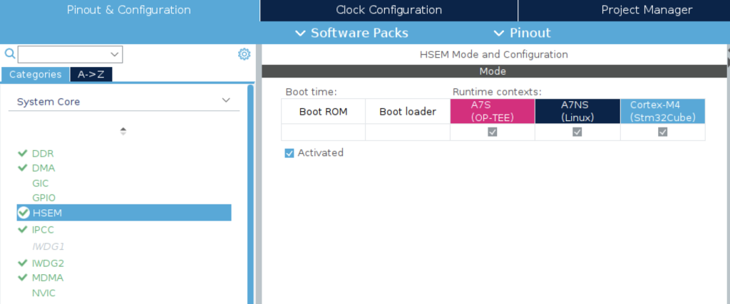
HSEM
Enable this for all runtime contexts:
IPCC
We will need this to allow communication between the Cortex-A7 MPU and the Cortex-M4 MCU, so enable it for all runtime contexts:
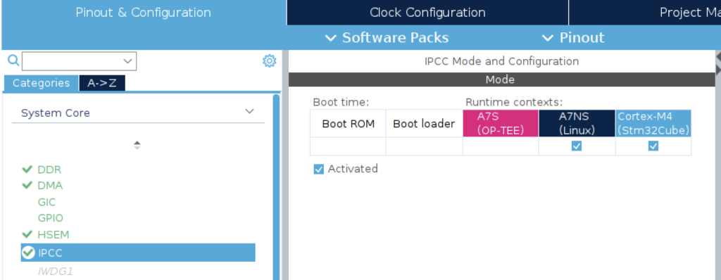
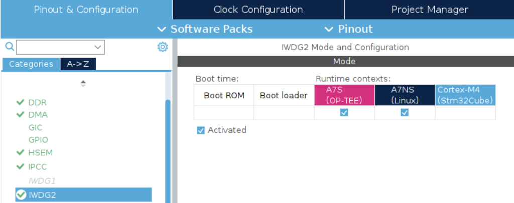
IWDG1 and IWDG2
These watchdog peripherals are available only to the Cortex-A7. They can run in all power modes and are independent of the main clock. So they are ideal for detecting early bring-up problems and we want to enable one. [https://wiki.st.com/stm32mpu/wiki/IWDG_internal_peripheral#Boot_time](Only the IWDG2 can be configured to automatically activate at startup (without any software intervention). So we will enable IWDG2:
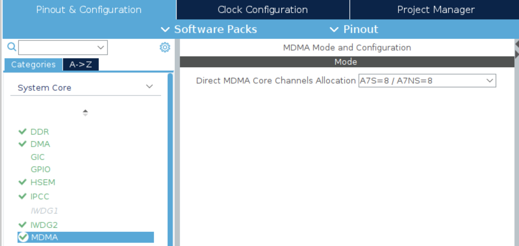
MDMA
Leave this using the default channel: A7S = 8 / A7NS = 8
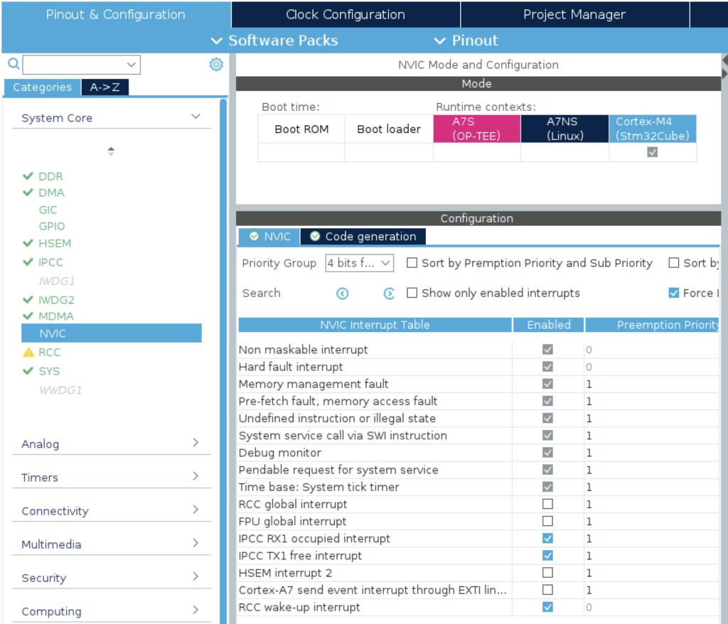
NVIC
Enable the Cortex-M4 support for IPCC interrupts:
- IPCC RX1 occupied interrupt
- IPCC TX1 free interrupt
RCC
The reset and clock controller is as important as it sounds, so we need it enabled across the entire runtime context. Enable the HSE and LSE. Don’t be tempted to design a board without a high speed internal clock!
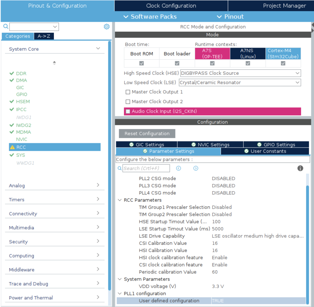
Note, if we want to manually configure the clock we need to set user defined configuration to TRUE.
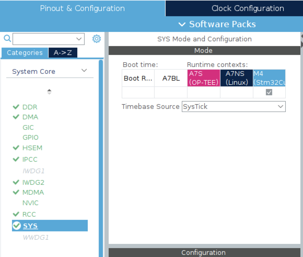
SYS
Enable the timebase for ther Cortex-M4. You can use systick for now.
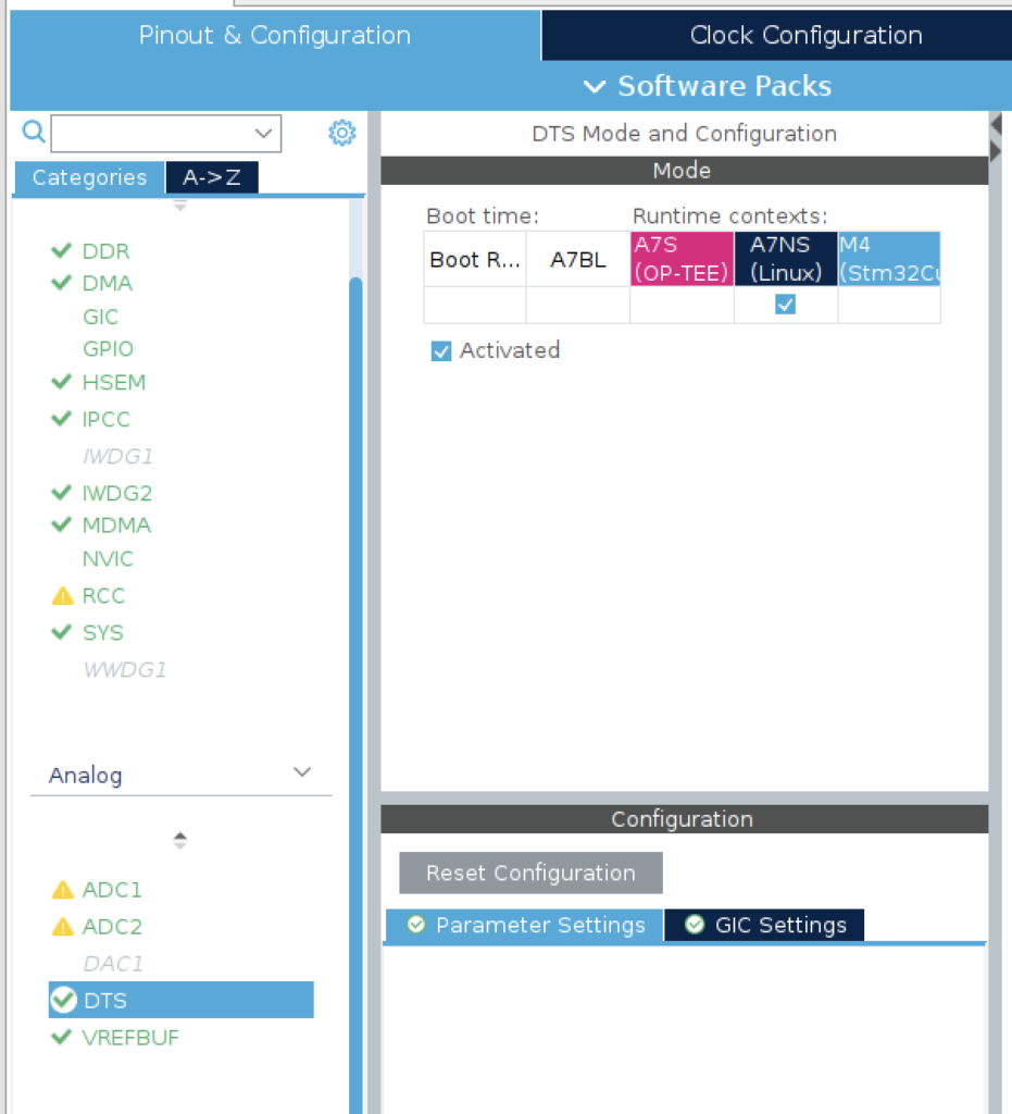
DTS
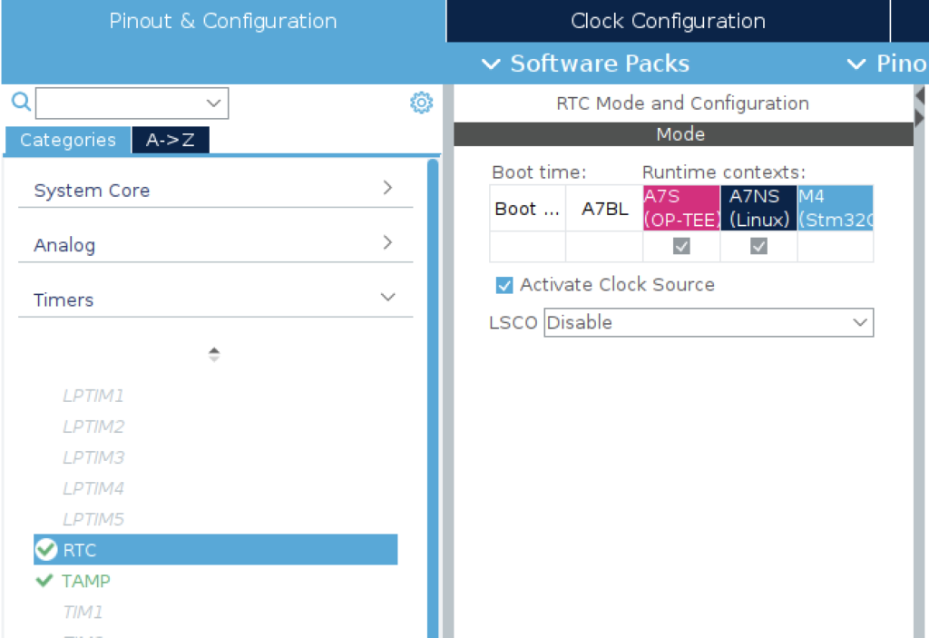
RTC
RTC needs to be enabled.
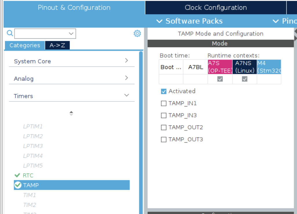
TAMP
The TAMP is used at boot time to share data between the ROM code, FSBL and SSBL: see backup registers for further information. No other configuration is needed.
SDMMC1 and/or SDMMC2
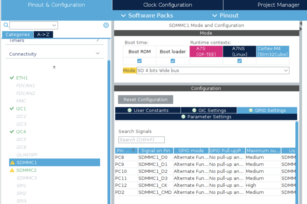
The image containing boot and linux binaries is loaded via µSD card so this is essential. Enable whichever interface is used on your board (or both).
Double check the pin for SDMMC_D2. It defaults to PE6, rather than PC10. PC10 keeps it with the rest of the SDMMC1 pins.
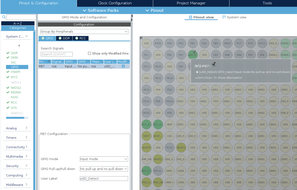
You may also need to configure an extra GPIO input pin for the auto-detect, if your µSD card connector supports it.
UART4
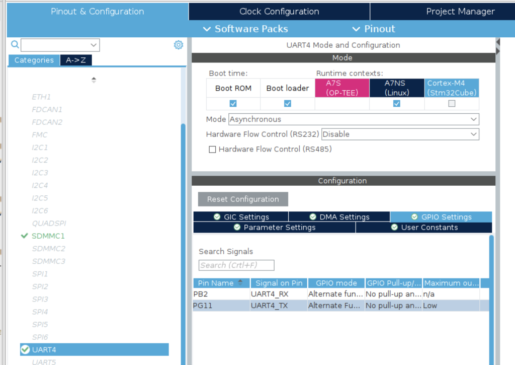
The second most important connectivity peripheral will allow a TTY session to the MPU so that you can monitor the boot progress. This will provide invaluable diagnostic info on troubleshooting bring-up issues:
You can probably pick any UART but UART4 seems to be the default so lets stick with convention. Make sure the GPIO pins match those on your board.
USB_HS1 and USB_HS2
Enable these if you want to use USB data connections. My board uses both so I enable both:
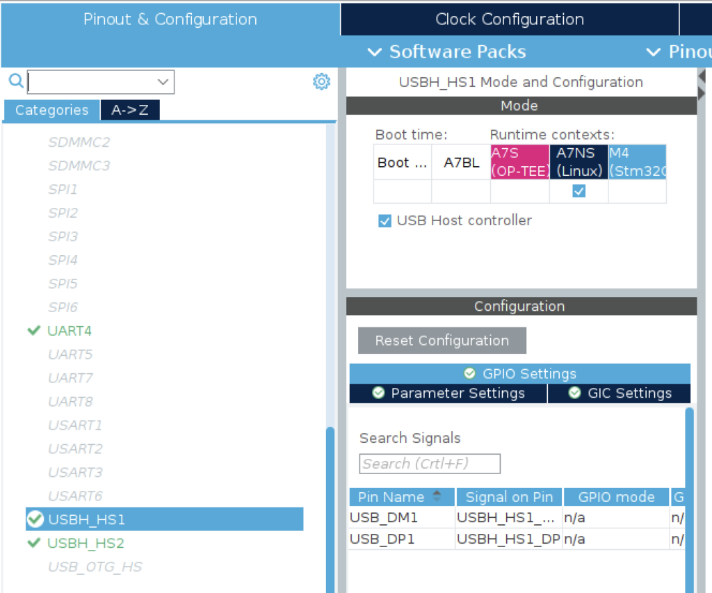
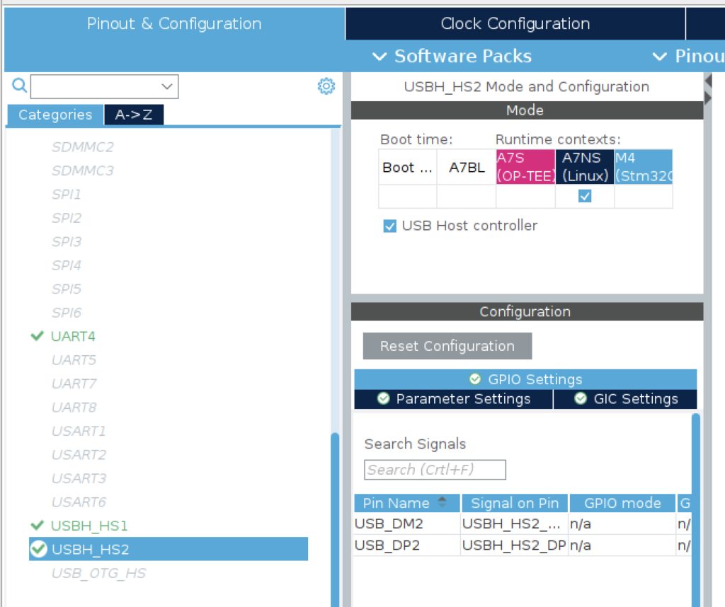
USB_OTG_HS
Enable these if you want to use USB Dual Role OTG or Type C data connections.
Note that these pins are shared with USB_HS2, so they cannot both be used:
The DK2 board gets around this by enabling multiple USB connections on USB_HS1 with a USB Hub IC (USB2514B-AEZC) and enabling the higher voltage requirements of USB-PD on USB_OTG_HS with an additional external USB PD Controller (STUSB1600).
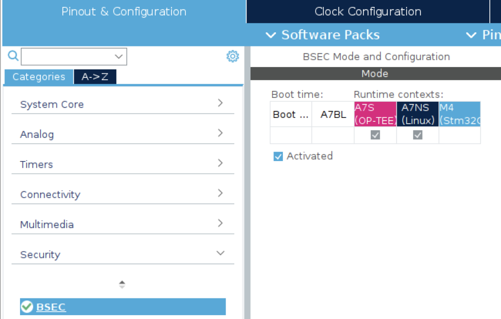
BSEC
This provides the boot security mechanism for OTP fuses and NVMEM. Enable this for A7S (OP-TEE) and A7NS (Linux) runtime contexts.
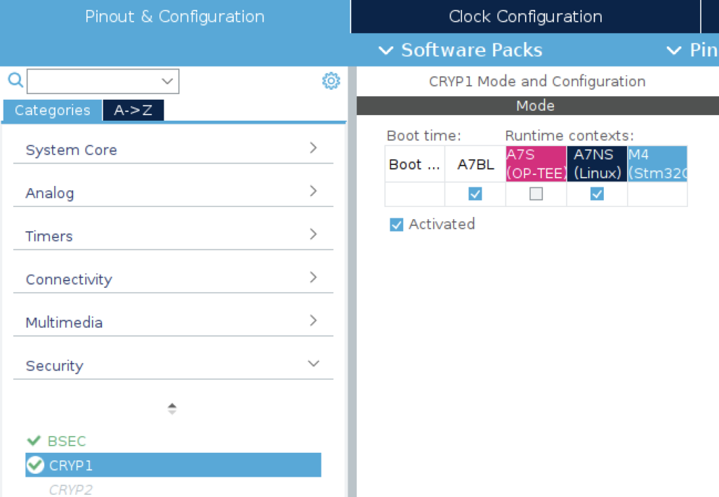
CRYP1
Enable for A7BL and the A7NS (Linux) runtime context for using in Linux® with Linux Crypto framework [*]
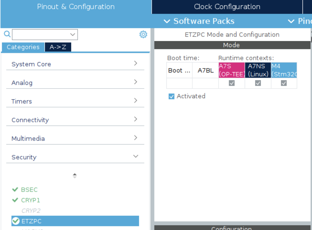
ETZPC
Enable Extend Trustzone Protection Controller for A7S (OP-TEE) and A7NS (Linux) runtime contexts.
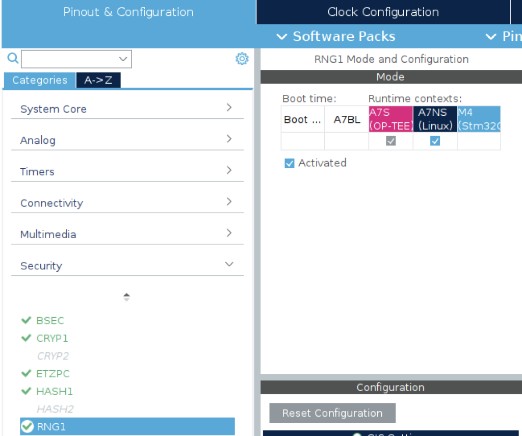
RNG
Enable Random Number Generator for A7S (OP-TEE) and A7NS (Linux) runtime contexts.
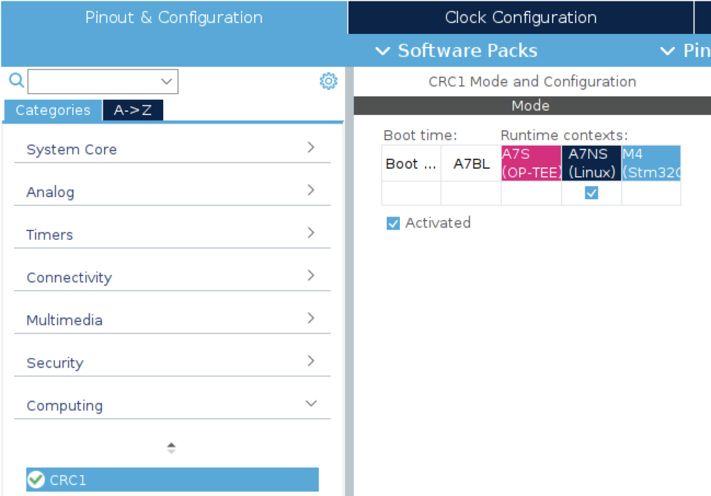
CRC1
Enable CRC for A7NS (Linux) runtime context.
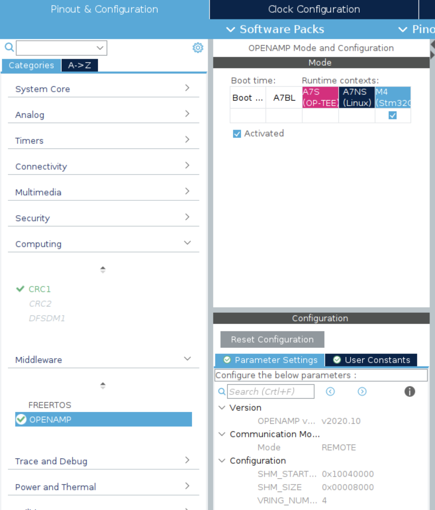
OPENAMP
This is a mechanism for IPCC from the Cortex-M4 end. Enable it for M4 (STM32) runtime context:
DEBUG
Enable this for the Cortex-M4 if you need serial debugging capabilities.
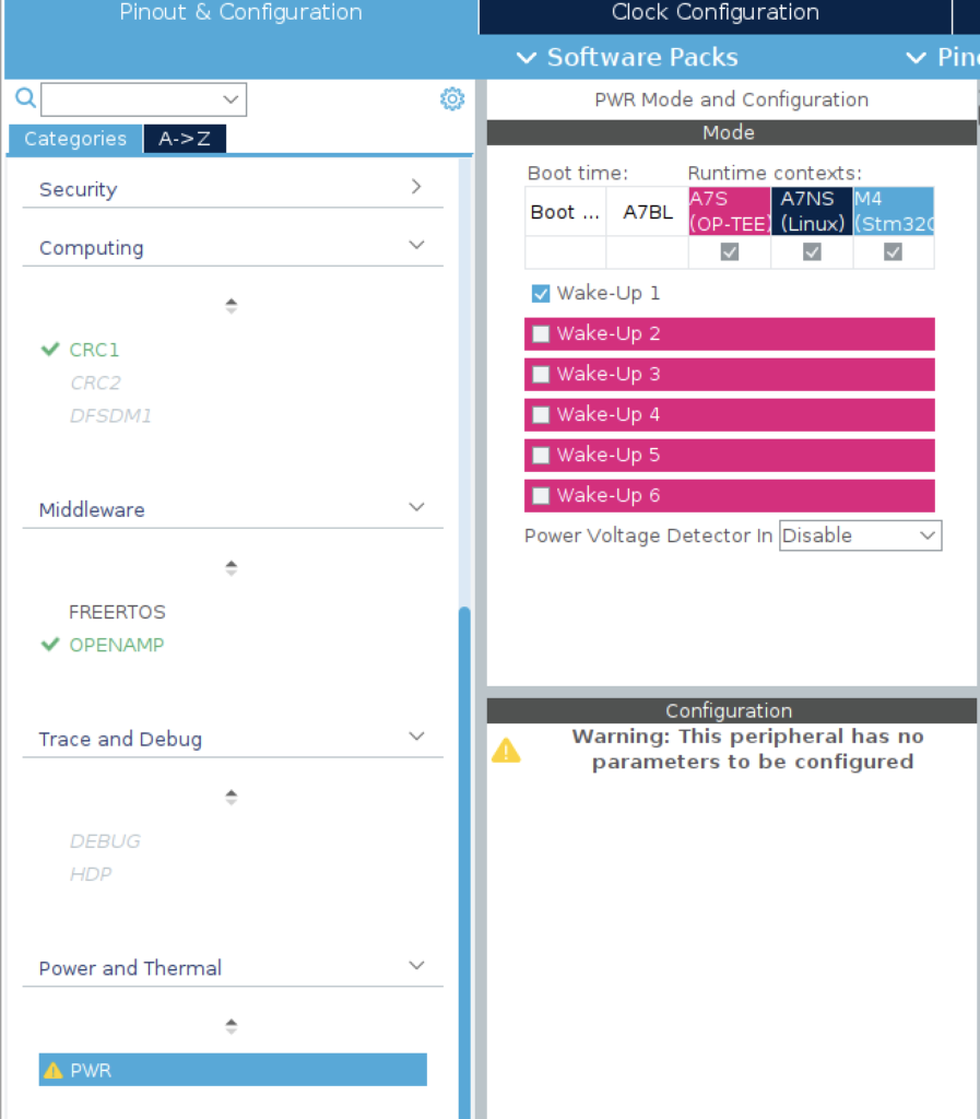
PWR
Enable this for A7S (OP-TEE). A7NS (Linux) and M4 (STM32) runtime contexts.
Enable the “Wakeup1” option. This is required during the BL32 boot stage.
B. Clock Configuration
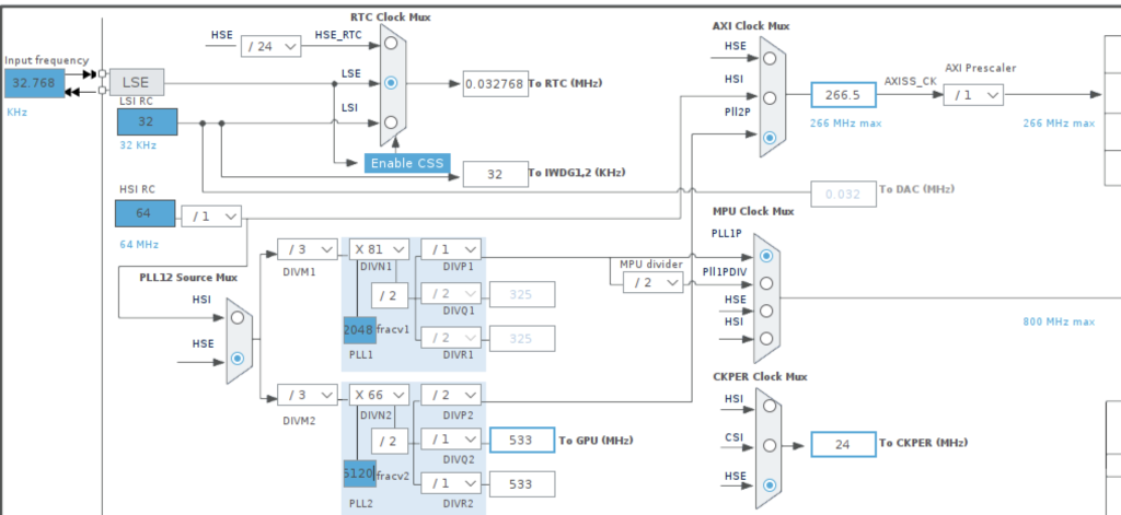
RTC Clock MUX and PLL12
- Set the RTC Clock MUX to LSE and PLL12 to HSE:
- PLL1_FRACV = 2048
- PLL2_FRACV = 5120
PLL3 and PLL4
- Set PLL3 and PLL4 Source MUX to HSE
- Set PLL3_FRACV = 6660
- Set PLL4_FRACV = 0

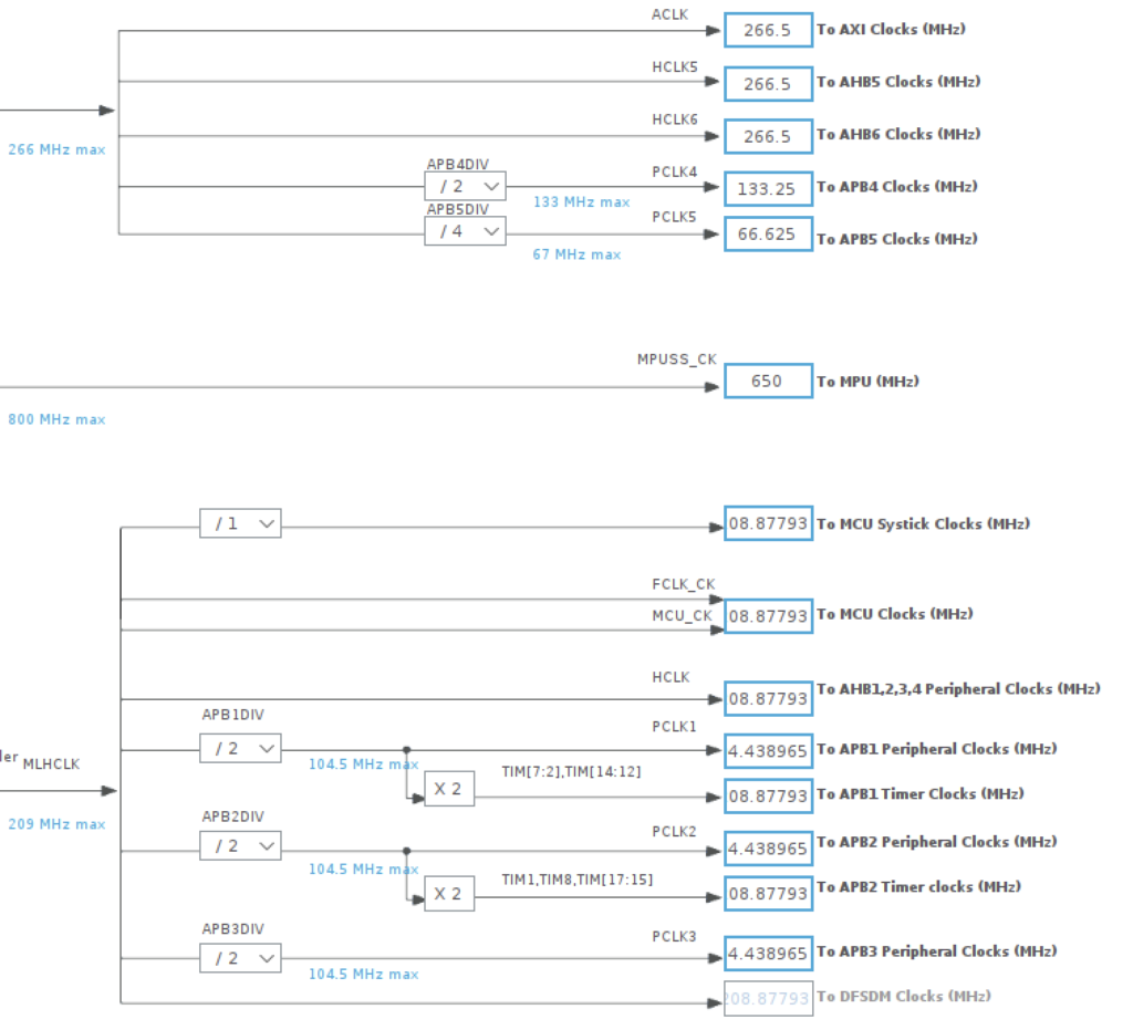
Peripheral Busses
- Peripheral busses should be set as follows:
SDMMC
- SDMMC1,2 can be set to 99MHz (from PLL4P)
MPUSS_CLK
- Set the MPUSS_CLK to 800MHz and press enter. Lock the value.
C. Device Tree properties
Device tree files are generated by STM32CubeIDE under the CA7 project:
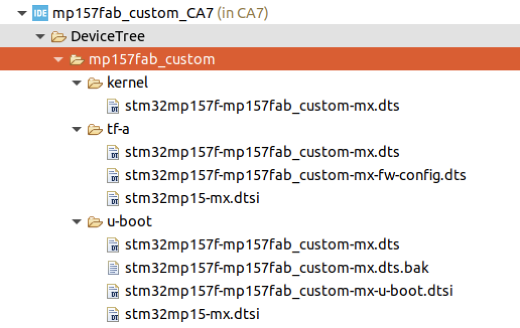
Each file has USER_CODE sections that require manual completion. There is some repetition here, but all sections are needed to boot the image.
KERNEL
Includes
/* USER CODE BEGIN includes */
#include <dt-bindings/gpio/gpio.h>
#include <dt-bindings/mfd/st,stpmic1.h>
#include <dt-bindings/rtc/rtc-stm32.h>
/* USER CODE END includes */
Reserved Memory
        /* USER CODE BEGIN reserved-memory */
        mcuram2:mcuram2@10000000{
            compatible = "shared-dma-pool";
            reg = <0x10000000 0x40000>;
            no-map;
        };

        vdev0vring0:vdev0vring0@10040000{
            compatible = "shared-dma-pool";
            reg = <0x10040000 0x1000>;
            no-map;
        };

        vdev0vring1:vdev0vring1@10041000{
            compatible = "shared-dma-pool";
            reg = <0x10041000 0x1000>;
            no-map;
        };

        vdev0buffer:vdev0buffer@10042000{
            compatible = "shared-dma-pool";
            reg = <0x10042000 0x4000>;
            no-map;
        };

        mcuram:mcuram@30000000{
            compatible = "shared-dma-pool";
            reg = <0x30000000 0x40000>;
            no-map;
        };

        retram:retram@38000000{
            compatible = "shared-dma-pool";
            reg = <0x38000000 0x10000>;
            no-map;
        };

        gpu_reserved:gpu@d4000000{
            reg = <0xd4000000 0x4000000>;
            no-map;
        };
        /* USER CODE END reserved-memory */
root
    /* USER CODE BEGIN root */
    usb_phy_tuning:usb-phy-tuning{
        st,hs-dc-level = <2>;
        st,fs-rftime-tuning;
        st,hs-rftime-reduction;
        st,hs-current-trim = <15>;
        st,hs-impedance-trim = <1>;
        st,squelch-level = <3>;
        st,hs-rx-offset = <2>;
        st,no-lsfs-sc;
    };

    aliases{
        serial0 = &uart4;
    };

    chosen{
        stdout-path = "serial0:115200n8";
    };

    vin: vin {
        compatible = "regulator-fixed";
        regulator-name = "vin";
        regulator-min-microvolt = <5000000>;
        regulator-max-microvolt = <5000000>;
        regulator-always-on;
    };

    // http://www.ti.com/lit/ds/symlink/tps54202.pdf
    vddcore: TPS54202 {

      compatible = "regulator-fixed";
      regulator-name = "vddcore";
      regulator-min-microvolt = <1350000>;
      regulator-max-microvolt = <1350000>;
      regulator-always-on;
      vin-supply = <&vin>;

    };

    // http://www.ti.com/lit/ds/symlink/tps54202.pdf
    vdd_ddr: TPS54202 {

        compatible = "regulator-fixed";
        regulator-name = "vdd_ddr";
        regulator-min-microvolt = <1350000>;
        regulator-max-microvolt = <1350000>;
        regulator-always-on;
        vin-supply = <&vin>;
    };

    // https://datasheet.lcsc.com/szlcsc/1912111437_Seaward-Elec-SE8233X2_C437587.pdf
    vdd: SE8233X2 {

        compatible = "regulator-fixed";
        regulator-name = "vdd";
        regulator-min-microvolt = <3300000>;
        regulator-max-microvolt = <3300000>;
        regulator-always-on;
        vin-supply = <&vin>;
    };

    // https://datasheet.lcsc.com/szlcsc/1912111437_Seaward-Elec-SE8233X2_C437587.pdf
    v3v3: SE8233X2 {

        compatible = "regulator-fixed";
        regulator-name = "v3v3";

        regulator-max-microvolt = <3300000>;
        regulator-always-on;
        vin-supply = <&vin>;

    };

    https://datasheet.octopart.com/DMG2302U-7-Diodes-Inc.-datasheet-103571615.pdf
    vdd_usb: DMG2302U {
        compatible = "regulator-fixed";
        regulator-name = "vdd_usb";
        regulator-min-microvolt = <3300000>;
        regulator-max-microvolt = <3300000>;
        regulator-always-on;
        vin-supply = <&v3v3>;
    };


    /* USER CODE END root */
m4-rproc
    /* USER CODE BEGIN m4_rproc */
    memory-region = <&retram>, <&mcuram>, <&mcuram2>, <&vdev0vring0>,
            <&vdev0vring1>, <&vdev0buffer>;
    interrupt-parent = <&exti>;
    interrupts = <68 1>;
    wakeup-source;
    /* USER CODE END m4_rproc */
sdmmc1
    /* USER CODE BEGIN sdmmc1 */
    cd-gpios = <&gpiob 7 (GPIO_ACTIVE_LOW | GPIO_PULL_UP)>;
    disable-wp;
    st,neg-edge;
    bus-width = <4>;
    vmmc-supply = <&v3v3>;
    /* USER CODE END sdmmc1 */
uart4
    /* USER CODE BEGIN uart4 */
    /delete-property/ dmas;
    /delete-property/ dma-names;
    /* USER CODE END uart4 */
usbh_ehci
    /* USER CODE BEGIN usbh_ehci */
    phys = <&usbphyc_port0>;
    /* USER CODE END usbh_ehci */
usbphyc_port0
    /* USER CODE BEGIN usbphyc_port0 */
    phy-supply = <&vdd_usb>;
    st,phy-tuning = <&usb_phy_tuning>;
    /* USER CODE END usbphyc_port0 */
usbphyc_port1
    /* USER CODE BEGIN usbphyc_port1 */
    phy-supply = <&vdd_usb>;
    st,phy-tuning = <&usb_phy_tuning>;
    /* USER CODE END usbphyc_port1 */
addons
/* USER CODE BEGIN addons */

&cpu0{
    cpu-supply = <&vddcore>;
};

&cpu1{
    cpu-supply = <&vddcore>;
};

&sram{

    dma_pool:dma_pool@0{
        reg = <0x50000 0x10000>;
        pool;
    };
};
/* USER CODE END addons */
TF-A
includes
/* USER CODE BEGIN includes */
#include <dt-bindings/power/stm32mp1-power.h>
/* USER CODE END includes */
root
    memory@c0000000{
        device_type = "memory";
        reg = <0xc0000000 0x20000000>;
    };

    aliases{
        serial0 = &uart4;
    };

    chosen{
        stdout-path = "serial0:115200n8";
    };

    vin: vin {
        compatible = "regulator-fixed";
        regulator-name = "vin";
        regulator-min-microvolt = <5000000>;
        regulator-max-microvolt = <5000000>;
        regulator-always-on;
    };

    // http://www.ti.com/lit/ds/symlink/tps54202.pdf
    vddcore: TPS54202 {

      compatible = "regulator-fixed";
      regulator-name = "vddcore";
      regulator-min-microvolt = <1350000>;
      regulator-max-microvolt = <1350000>;
      regulator-always-on;
      vin-supply = <&vin>;

    };

    // http://www.ti.com/lit/ds/symlink/tps54202.pdf
    vdd_ddr: TPS54202 {

        compatible = "regulator-fixed";
        regulator-name = "vdd_ddr";
        regulator-min-microvolt = <1350000>;
        regulator-max-microvolt = <1350000>;
        regulator-always-on;
        vin-supply = <&vin>;
    };

    // https://datasheet.lcsc.com/szlcsc/1912111437_Seaward-Elec-SE8233X2_C437587.pdf
    vdd: SE8233X2 {

        compatible = "regulator-fixed";
        regulator-name = "vdd";
        regulator-min-microvolt = <3300000>;
        regulator-max-microvolt = <3300000>;
        regulator-always-on;
        vin-supply = <&vin>;
    };

    // https://datasheet.lcsc.com/szlcsc/1912111437_Seaward-Elec-SE8233X2_C437587.pdf
    v3v3: SE8233X2 {

        compatible = "regulator-fixed";
        regulator-name = "v3v3";

        regulator-max-microvolt = <3300000>;
        regulator-always-on;
        vin-supply = <&vin>;

    };

    https://datasheet.octopart.com/DMG2302U-7-Diodes-Inc.-datasheet-103571615.pdf
    vdd_usb: DMG2302U {
        compatible = "regulator-fixed";
        regulator-name = "vdd_usb";
        regulator-min-microvolt = <3300000>;
        regulator-max-microvolt = <3300000>;
        regulator-always-on;
        vin-supply = <&v3v3>;
    };

    /* USER CODE END root */
bsec
    /* USER CODE BEGIN bsec */
    board_id:board_id@ec{
        reg = <0xec 0x4>;
        st,non-secure-otp;
    };
    /* USER CODE END bsec */
pwr_regulators
    /* USER CODE BEGIN pwr_regulators */
    system_suspend_supported_soc_modes = <
        STM32_PM_CSLEEP_RUN
        STM32_PM_CSTOP_ALLOW_LP_STOP
        STM32_PM_CSTOP_ALLOW_STANDBY_DDR_SR
    >;
    system_off_soc_mode = <STM32_PM_CSTOP_ALLOW_STANDBY_DDR_OFF>;
    vdd-supply = <&vdd>;
    vdd_3v3_usbfs-supply = <&vdd_usb>;
    /* USER CODE END pwr_regulators */
addons
/* USER CODE BEGIN addons */
&cpu0{
    cpu-supply = <&vddcore>;
};

&cpu1{
    cpu-supply = <&vddcore>;
};

&nvmem_layout{
    nvmem-cells = <&cfg0_otp>,
            <&part_number_otp>,
            <&monotonic_otp>,
            <&nand_otp>,
            <&uid_otp>,
            <&package_otp>,
            <&hw2_otp>,
            <&pkh_otp>,
            <&board_id>;
    nvmem-cell-names = "cfg0_otp",
            "part_number_otp",
            "monotonic_otp",
            "nand_otp",
            "uid_otp",
            "package_otp",
            "hw2_otp",
            "pkh_otp",
            "board_id";
};

&timers15{
    secure-status = "okay";
    st,hsi-cal-input = <7>;
    st,csi-cal-input = <8>;
};
/* USER CODE END addons */
OPTEE
Duplicate/copy the entire TF-A directory to the device tree directory. Rename the directory from “tf-a” to “optee-os”.
Open the new optee “stm32mp157f-mp157fab_custom-mx.dts” file and comment out the ddr include. Its not needed and will cause a build error with bitbake.
The end result should look like this:

U-BOOT
includes
/* USER CODE BEGIN includes */
#include <dt-bindings/gpio/gpio.h>
#include <dt-bindings/mfd/st,stpmic1.h>
#include <dt-bindings/rtc/rtc-stm32.h>
/* USER CODE END includes */
Reserved memory
        /* USER CODE BEGIN reserved-memory */
        mcuram2:mcuram2@10000000{
            compatible = "shared-dma-pool";
            reg = <0x10000000 0x40000>;
            no-map;
        };

        vdev0vring0:vdev0vring0@10040000{
            compatible = "shared-dma-pool";
            reg = <0x10040000 0x1000>;
            no-map;
        };

        vdev0vring1:vdev0vring1@10041000{
            compatible = "shared-dma-pool";
            reg = <0x10041000 0x1000>;
            no-map;
        };

        vdev0buffer:vdev0buffer@10042000{
            compatible = "shared-dma-pool";
            reg = <0x10042000 0x4000>;
            no-map;
        };

        mcuram:mcuram@30000000{
            compatible = "shared-dma-pool";
            reg = <0x30000000 0x40000>;
            no-map;
        };

        retram:retram@38000000{
            compatible = "shared-dma-pool";
            reg = <0x38000000 0x10000>;
            no-map;
        };

        gpu_reserved:gpu@d4000000{
            reg = <0xd4000000 0x4000000>;
            no-map;
        };
        /* USER CODE END reserved-memory */
root
    /* USER CODE BEGIN root */
    usb_phy_tuning:usb-phy-tuning{
        st,hs-dc-level = <2>;
        st,fs-rftime-tuning;
        st,hs-rftime-reduction;
        st,hs-current-trim = <15>;
        st,hs-impedance-trim = <1>;
        st,squelch-level = <3>;
        st,hs-rx-offset = <2>;
        st,no-lsfs-sc;
    };

    aliases{
        serial0 = &uart4;
    };

    chosen{
        stdout-path = "serial0:115200n8";
    };

    vin: vin {
        compatible = "regulator-fixed";
        regulator-name = "vin";
        regulator-min-microvolt = <5000000>;
        regulator-max-microvolt = <5000000>;
        regulator-always-on;
    };

    // http://www.ti.com/lit/ds/symlink/tps54202.pdf
    vddcore: TPS54202 {

      compatible = "regulator-fixed";
      regulator-name = "vddcore";
      regulator-min-microvolt = <1350000>;
      regulator-max-microvolt = <1350000>;
      regulator-always-on;
      vin-supply = <&vin>;

    };

    // http://www.ti.com/lit/ds/symlink/tps54202.pdf
    vdd_ddr: TPS54202 {

        compatible = "regulator-fixed";
        regulator-name = "vdd_ddr";
        regulator-min-microvolt = <1350000>;
        regulator-max-microvolt = <1350000>;
        regulator-always-on;
        vin-supply = <&vin>;
    };

    // https://datasheet.lcsc.com/szlcsc/1912111437_Seaward-Elec-SE8233X2_C437587.pdf
    vdd: SE8233X2 {

        compatible = "regulator-fixed";
        regulator-name = "vdd";
        regulator-min-microvolt = <3300000>;
        regulator-max-microvolt = <3300000>;
        regulator-always-on;
        vin-supply = <&vin>;
    };

    // https://datasheet.lcsc.com/szlcsc/1912111437_Seaward-Elec-SE8233X2_C437587.pdf
    v3v3: SE8233X2 {

        compatible = "regulator-fixed";
        regulator-name = "v3v3";

        regulator-max-microvolt = <3300000>;
        regulator-always-on;
        vin-supply = <&vin>;

    };

    https://datasheet.octopart.com/DMG2302U-7-Diodes-Inc.-datasheet-103571615.pdf
    vdd_usb: DMG2302U {
        compatible = "regulator-fixed";
        regulator-name = "vdd_usb";
        regulator-min-microvolt = <3300000>;
        regulator-max-microvolt = <3300000>;
        regulator-always-on;
        vin-supply = <&v3v3>;
    };


    /* USER CODE END root */
m4_rproc
    /* USER CODE BEGIN m4_rproc */
    memory-region = <&retram>, <&mcuram>, <&mcuram2>, <&vdev0vring0>,
            <&vdev0vring1>, <&vdev0buffer>;
    interrupt-parent = <&exti>;
    interrupts = <68 1>;
    wakeup-source;
    /* USER CODE END m4_rproc */
sdmmc1
    /* USER CODE BEGIN sdmmc1 */
    cd-gpios = <&gpiob 7 (GPIO_ACTIVE_LOW | GPIO_PULL_UP)>;
    disable-wp;
    st,neg-edge;
    bus-width = <4>;
    vmmc-supply = <&v3v3>;
    /* USER CODE END sdmmc1 */
uart4
    /* USER CODE BEGIN uart4 */
    /delete-property/ dmas;
    /delete-property/ dma-names;
    /* USER CODE END uart4 */
usbh_ehci
    /* USER CODE BEGIN usbh_ehci */
    phys = <&usbphyc_port0>;
    /* USER CODE END usbh_ehci */
usbphyc_port0
    /* USER CODE BEGIN usbphyc_port0 */
    phy-supply = <&vdd_usb>;
    st,phy-tuning = <&usb_phy_tuning>;
    /* USER CODE END usbphyc_port0 */
usbphyc_port1
    /* USER CODE BEGIN usbphyc_port1 */
    phy-supply = <&vdd_usb>;
    st,phy-tuning = <&usb_phy_tuning>;
    /* USER CODE END usbphyc_port1 */
addons
/* USER CODE BEGIN addons */

&cpu0{
    cpu-supply = <&vddcore>;
};

&cpu1{
    cpu-supply = <&vddcore>;
};

&sram{

    dma_pool:dma_pool@0{
        reg = <0x50000 0x10000>;
        pool;
    };
};
Generate the code in the tool.
Now we are ready to attempt an image build using Yocto/Bitbake.
