Page Contents
Block diagram – System Overview
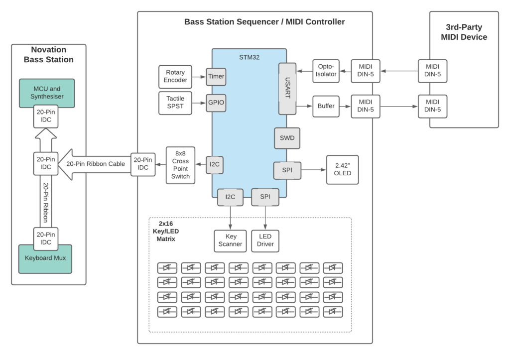
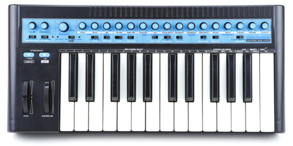
The step sequencer will be interface with the Novation BassStation via the ribbon cable on the left, with optional support for 3rd devices via a MIDI interface on the right. This will allow the sequencer to be reused for other MIDI-supported devices.

Microcontroller pinout
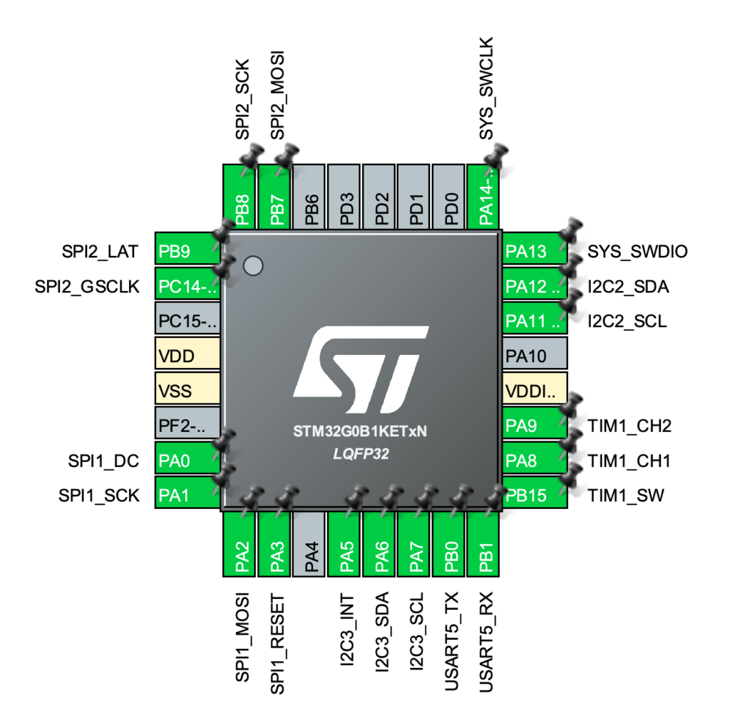
The microcontroller pinout specifics are shown below

System MCU pinout mapping
And here you can see how the microcontroller maps into the rest of the system:
System schematics
| Power Supply Overview |
|---|
| The system takes a 9-15V input. This first goes through a PMOS based polarity protection block. Then it is split between two buck converters that regulate the voltage down to 5V. 5V_RGB is dedicated to the LED drivers for the user keys since this requires ~3A. 5V_MISC is used for the MIDI interface and other sub systems. This 5V rail is further regulated down to 3.3v using LDOs for the OLED and MCU subsystems. |
| Sequencer Input Keys |
|---|
| This sheet is a bit cramped However, the user keys (small sub-blocks shown on the right) share both LED and user input switch function so it makes sense to put the related circuitry together. The TLC5955’s drive the two banks of RGB LEDs. The ADP5587 multiplexes/scans the input for the user keys. The preset write and write protection switches are also shown here since the ADP5587 can use leftover pins for GPIO functions. |
| Crosspoint output |
|---|
| The ADG2188 controls the triggering of the Novation keyboard via a serial interface. The ICs are expensive but massively simplify the design. |
| MIDI Interface |
|---|
| Standard layout for a MIDI interface. Note the double inverter has been replaced by a single buffer (74LVC1G34). |
| Microcontroller |
|---|
| The power scheme for the STM32G0B1 is simple and only requires a few decoupling caps. This schematic mirrors the pinout diagram shown above. The rotary encoder and debug sub-blocks are also located here. Since the SWDCLK pin also functions as the BOOT pin, an optional pulldown or pullup resistor can be used. |
Layout 3D render
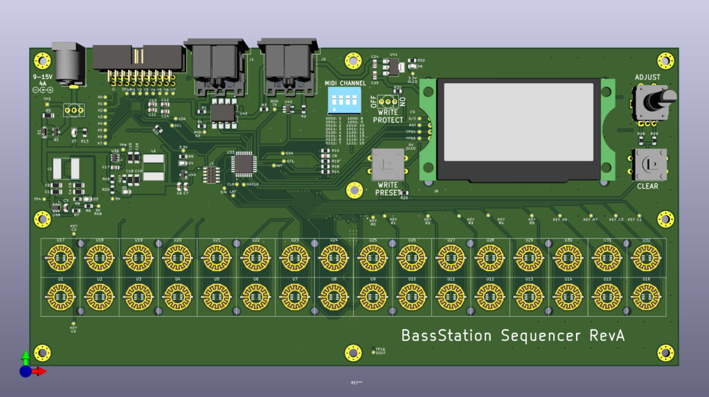
And the final design can be seen below! Now to wait for the PCB fabrication….

Interactive BOM can be found here.
