Front panel design
So lets talks about how we want the front panel to be laid out.
Lets start with the connector interface:
- 20-Pin Ribbon cable connector for the synth interface switching.
- Power (in the form of a barrel connector).
- MIDI in/out (for future compatibility with 3rd party devices).
Convention says we put these connectors at the back for easy access.
What about the actual user interface though?
We want to be able to:
- Enable/dIsable a step in the sequence.
- Set the note/pitch for a step.
- Set the duration of the step. Optionally we could hard limit each step to length=1.
- Set the tempo or speed that the sequencer is run.
- Select a preset slot to play a saved sequencer pattern from.
- Write the current sequencer pattern to the current selected preset slot.
- Write enable/disable to protect accidental overwrite of a saved pattern.
- Select the MIDI channel.
- A display to show the value of settings and the current mode.
- The step keys should illuminate different colours. Red for selected step and green for current sequencer position.
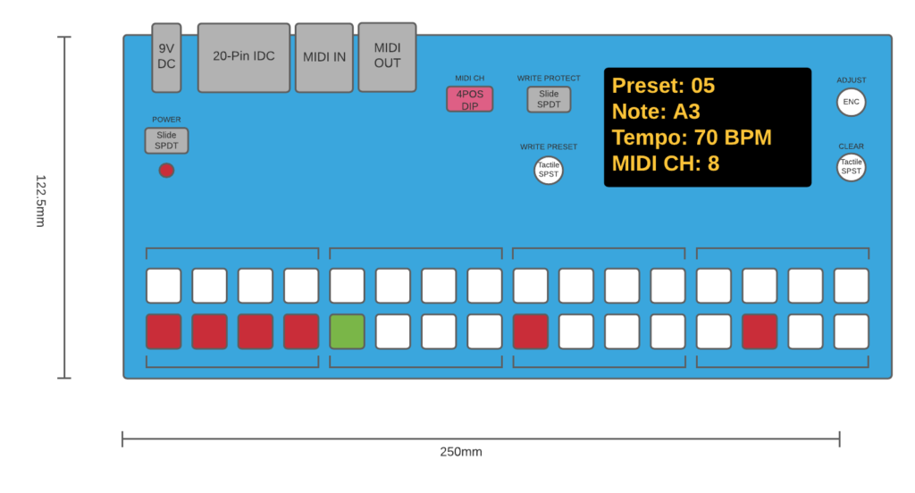
Here is a mockup of the front panel and an explanation below:

The “adjust” encoder is the main control. It also has a SPST switch built in which is activated by pushing down on the knob. With this control and the display, the control options are (almost) endless. I would have preferred to have had more than one encoder to make it easier to use, and the MCU certainly supported more than one. However, enabling more than one encoder prevented contiguous pin mapping for the serial interfaces (SPI, I2C, USART). i.e. the pins would not be grouped together, which would make the PCB layout much trickier/messier. From an electronic design point-of-view this makes sense, but from a user design point-of-view, I may regret this decision.
The default “start/tempo” mode will start/stop the sequencer when the “adjust” knob switch is pressed and will change the tempo when the “adjust” knob is increased/decreased.
When a step is selected, the key will illuminate and the mode will change to “pitch” selection. The user can then select the note/pitch of the newly selected step. The selected note will be shown on the display. The note/pitch selected will be set when the user presses the “adjust” knob switch. The mode then reverts back to default “start/tempo” mode. Once the step note is set, it can only be set again by first deselecting the step. This clears the step key illumination and its settings.
The write preset and write protect inputs will be a SPST tactile switch and toggle SPDT switch, respectively. When the write preset switch is pressed for less than 1sec, the currernt pattern can be selected from a list of preset slots using the “adjust” knob. The selected preset slot is loaded when the “adjust” knob switch is pressed. When the write protect switch is pressed for more than 1sec, the current pattern is written to the selected preset slot. When the write protect switch is enabled, the write preset switch has no effect.
The crosspoint switch IC had a reset pin, so I figured it would be useful to breakout this out to the front panel. This will simultaneously reset all the crosspoint switch connections, effectively muting the output on all steps.
The MIDI channel should be selected and then restarted. The MCU will check the value on system boot. The selector will be a 4 way DIP switch since these are cheap and widely available. A legend depicting the four bit word values and their decimal translation will be required.
There is also a power switch with LED to indicate when the device is powered on.
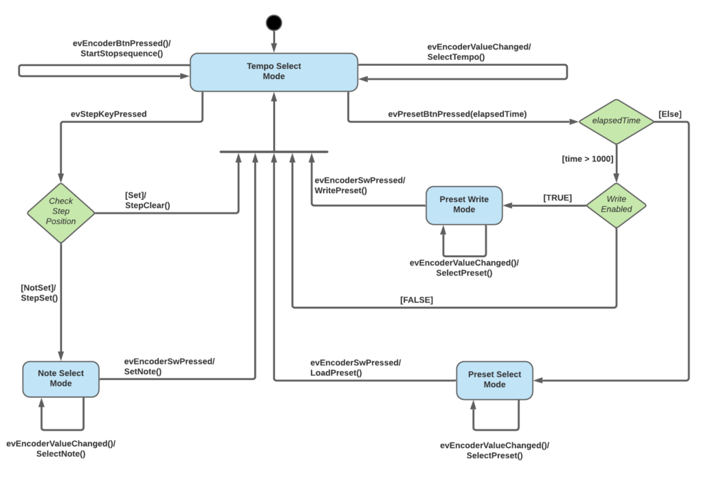
Here is a statechart showing the described user interface behavior.

