Page Contents
Designing the sequencer
So whats next? Well we need some way to set the steps on the sequencer.
I want 16 steps per bar, each step can be illumintated by the user, with an ability to set the note (and the duration). The sequencer runs through the individual steps at a given tempo, triggering the notes via some kind of output interface (CV, MIDI or electrical switching in our case).
Switches. Some kind of single pole, single throw switch. It can be latching or momentary (a microcontroller can handle the latching). Needs to be illuminated to tell the user that its been set. Illuminated mechanical switches can be expensive. How about a silicon membrane with PCB traces for the switch contacts? An LED can sit inside these and light when they are pressed (again, the micrcontroller will handle this)
Silicon Rubber
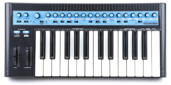
Something like the Ableton Push?
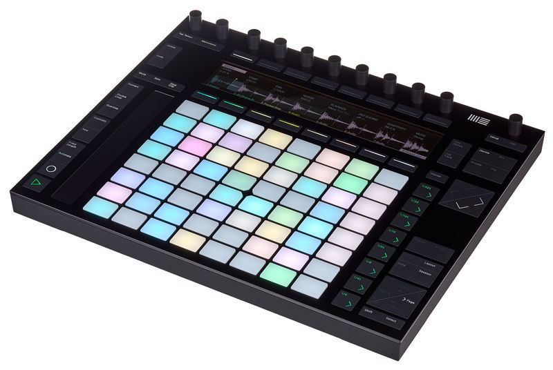
The switch contacts are closed by carbon pads. Either inset into the silicon membrane or as a separate mylar sheet. Happily I quickly stumbled across this adafruit product:
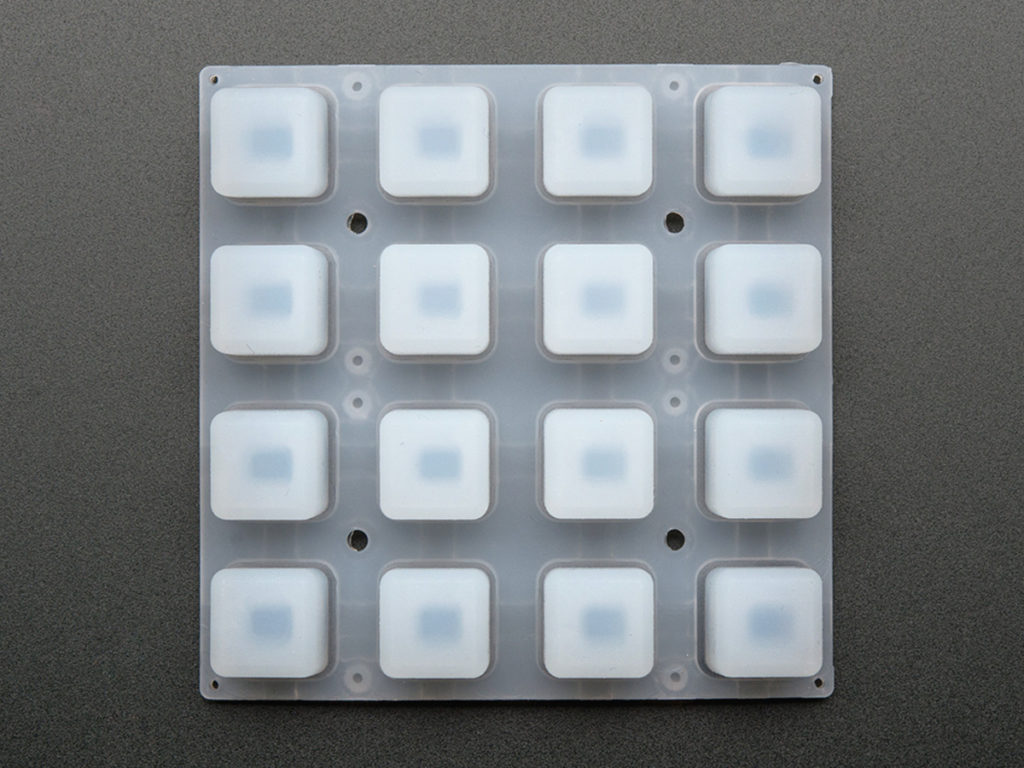
You can see on this image how the LED can sit within the switch contacts and the carbon ring on the underside of the membrane connects the traces to close the switch:
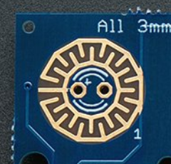
It even comes with a sample PCB with footprint for the switch contacts and CAD drawing for the membrane. Bonus. Thanks Adafruit!
Their example uses the HT16K33 IC. This handy chip has a dual function: 1) drive all 16 LEDs and 2) scan a 10×3 keypad. I was all ready to jump into a design using this chip. But then I realised this chip only supports single colour LEDs. I want RGB LEDs!
Seems this dual function chip is a rarity. There is another one by Linear (RIP), but to drive 16 LEDs, let alone 16 RGB LEDs I’m going to have to find separate LED driver and keyscanning solutions.
Keyscanning
Now keyscanning….this is something we could do natively on the microcontroller. After all, 16 pins is not a lot for a 100pin MCU. I was planning to use a 32pin MCU however, and burdening the MCU with the keyscanning operation (along with all the other things it has to do) might be a decision I come to regret.
So I came across another Analog Device Chip, the ADP5587:
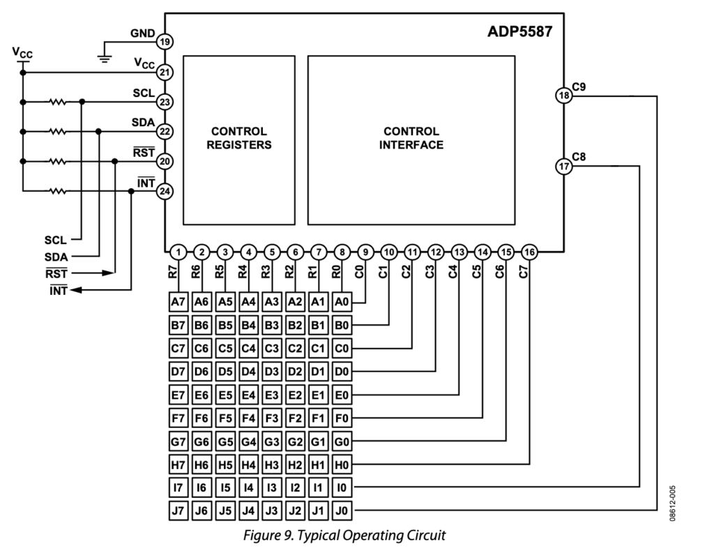
This will scan key presses in an 8×10 matrix. Well, I can use that for 16 buttons no problem. It also doubles as a GPIO expander. i.e. any unused pins can be used as GPIO….very handy.
RGB LED Driver
I recall a great hackaday talk with Mike Harrison where he recommended the 12 channel TI TLC5971. That’s a nice chip, but if we want 16 steps using RGB then we need to control 48 LEDS. It seems that’s a common number because TI also do a similar 48-channel version: the TLC5955
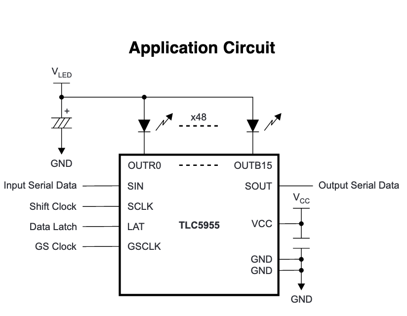
Ok this is promising. PWM control on each LED channel using grayscale brightness (65,536 steps). It uses a SPI interface…of sorts, which has a 769-bit long data shift register….well i guess thats not surprising given 48 channels. Constant current can be controlled via the SPI interface also…..ah yeah current consumption:
Here is the datasheet equation for calculating the current consumption per colour group.
Its much scarier than it looks.

Assuming that DCXn (the “dot correction” constant current setting) and BCX (the “brightness control” settings) are at their maximum setting i.e. 127. Then both bracketed terms equal 1!
I_{OUTn} = I_{OLCMax}\times(0.262 + 0.738 \times \frac {127}{127} )\times(0.1 + 0.9 \times \frac{127}{127})
I_{OUTn} = I_{OLCMax}\times(1)\times(1)
Not so scary now, huh?
I_{OLCMax} is the max current for each LED. Which is 39.1mA
so for 16 LEDs, current consumption per colour grouping is:
39.1 \times 16 = \underline{510.4} mA
But we have 3 colour groupings so the final number is:
510.4 \times 3 = \underline{1531.2} mA
Multicolour shiny things
Finally lets not forget the RGB LEDs. I want to use surface mount LEDs, they need to fit within the 3mm inner circle of the PCB switch traces and they need to contain three spearate LEDs in a single package.
I chose these Cree CLY6D-FKC.
The knee voltage of the LED driver is low (0.7v) and i’m running each colour LED with 5V VLED so i don’t anticipate any problems with forward voltage.
The absolute max forward current of the blue and green LED components are less than the max current sink capabilities of the driver and there are no series resistors. So I need to take care during tests that I don’t accidentally overload these LEDs.
Since these LEDs don’t have a white component, achievieng a white colour will take siginificant current since it uses all three RGB components at once.
Moving the goalposts
Ok so we already upgraded the single colour LEDs to RGB LEDs.
When I said 16 steps was enough, it was suggested “why not 32 steps?”.
Nah that’s silly…..no wait!?
LET’S DO 32 STEPS!!!
The ADP5587 can handle many more inputs. We just need to use two more common pins.
We would need an extra TLC5955 to handle the extra 48 channels. Its SPI controlled so we just keep clockin that data on down the line. The current consumption would now be doubled to 3062.4 mA. Ok thats still doable, but lets stop ignoring the elephant in the room. Next time, we tackle the power supply.
