Intro
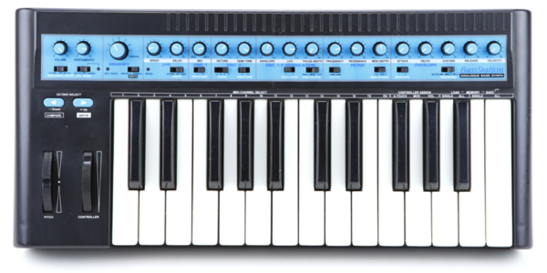
I just scored this original Novation BassStation synth on Ebay. It’s a hybrid synth that uses digital timing control courtesy of an MCU (Panasonic MN1883217) to control two analog oscilators. Legend tells that it has a richer sound than the rack mounted version. Well, i’m not qualified to verify such claims, but it is very fat sounding indeed.
Either it has a slight latency (well it was the 90’s) or my keyboard skills are poor (more likely), but playing fast bass lines is tricky.
It does support MIDI but its rather limited. It doesn’t receive note information, only program select, envelope and filter settings. So MIDI is not an option.
It has no internal sequencer. Lets build one!
Hatching a plan
I thought about replacing the MCU (some kind of footprint adaptor?) but you would have to rewrite all the firmware blind. Its a lot of work and no guarantee that you don’t wreck the entire synth. Nah thats a nuts idea.
Then I saw the keyboard connector. If I can figure out how the signals are being sent from the keyboard to the MCU via this cable then maybe I can inject my own signals from an external device!
I can connect an auxiliary ribbon cable to this one and design an external MIDI interface to trigger those signals. Better yet, lets build a sequencer that triggers the signals directly!
Examining the Keyboard PCB
The connector uses a ribbon cable with a 20 pin IDC connector. This isn’t enough pins for the entire keyboard – the keyboard has 25 keys. So there is probably some multiplexing being used where the MCU is scanning the keypresses just like on a keyboard. I need to understand more about how this multiplexing is being used.
WIth the cable unplugged from the main board I measured the voltages on the connector. Four were unconnected, the rest were at 5V. I tried shorting some to ground (a little risky perhaps). No notes were forthcoming. I tried connecting some of the pins together. Still nothing.
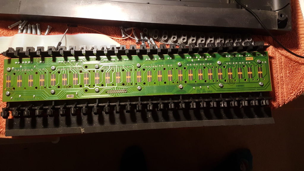
I decided to take the keys off and investigate further. There is a PCB underneath the keyboard. The keys use a carbon membrane for switches much like a calculator. Note that each key has two membrane switches. Maybe different velocity? Maybe On and Off?

On the underside of the PCB there are a number of diodes in series with each switch contact. Perhaps the MCU detects the diode drop when some of the pins are shorted together? When I tried shorting the pins earlier I only tried a few combinations.
I tried this again. Shorting different pin combinations on the connector I heard notes! Aha! I decided to map out the connections on the ribbons before continuing.
Mapping the keyboard connector interface
The top row of the connector are connected to eight groups of the keys as “common”. The bottom row pins are as eight switch positions, each one is used 3-4 times on the keyboard, usually spaced eight keys apart.

The mapping of these pins to the keys themselves are as follows:

So for example, you can connect pins SW1-SW8 in turn to COM Pin 9 to hear notes E to C. Connecting the same pins to COM Pin 11 made no sound, so for the moment I will assume these are Off signals for when the key is lifted. They are positioned further back on the PCB so this makes sense.
Now we understand how the keyboard triggers the individual notes on the synth we can design an external device to trigger these notes programmatically!
