Overview
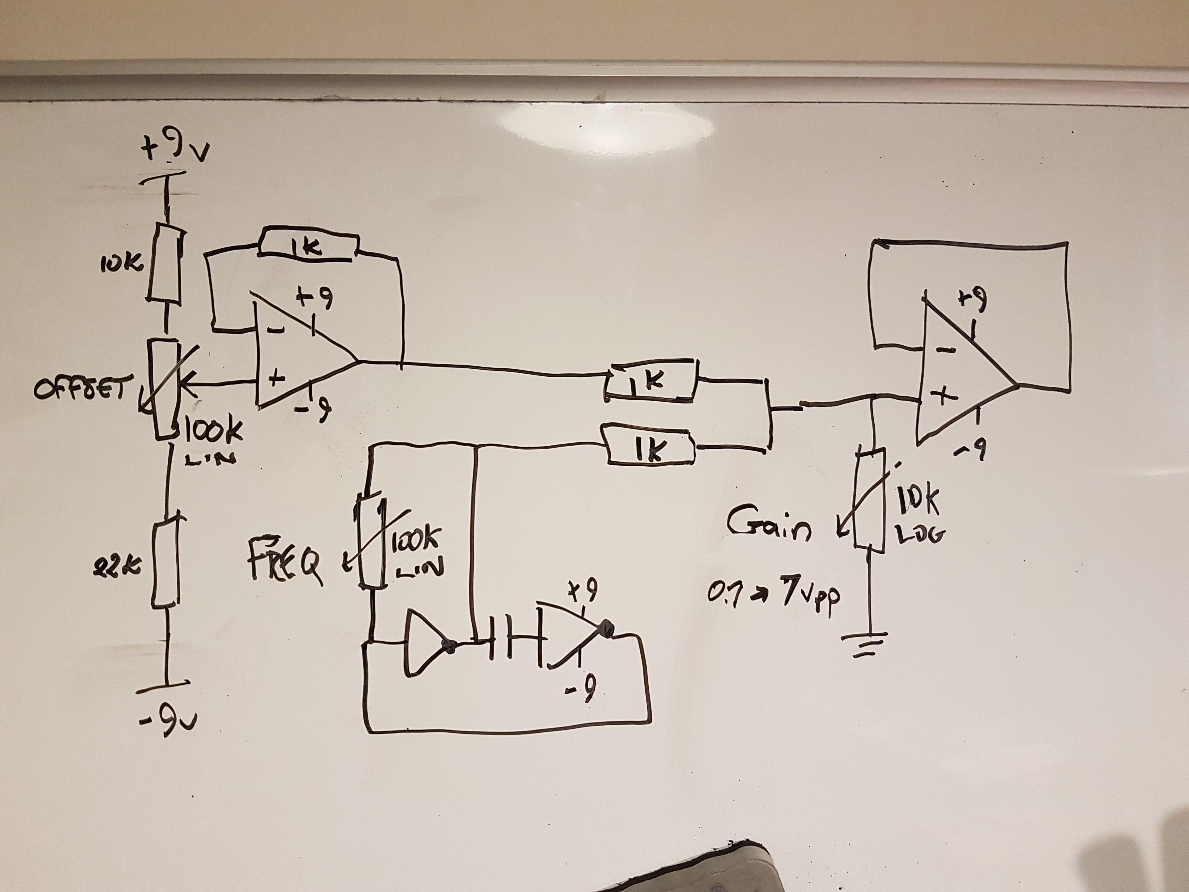
Each of these designs use a TC4667 charge pump to create a negative voltage from a +9VDC supply. DC offset adjustment of the AC output signal is attained via the +/- voltage divider OFFSET potentiometer. This is summed along with the generated waveform. The amplitude of the output waveform is determined by the feedback network on the non-inverting leg of the last op amp, controlled by the GAIN potentiometer. You can use a dual supply with the hex inverter IC to attain offset above/below ground.
<strong>1. Dual Inverter square wave Generator</strong>


    <img src="https://bitshiftjo.cluster026.hosting.ovh.net/wp-content/uploads/2018/09/20180103_150457-1024x768.jpg" alt="" width="525" height="394" class="alignnone size-large wp-image-538" />

    This is a typical dual-inverter square wave generator. The RC network controls the frequency of the generated waveform, with the FREQ pot allowing direct user control. To control the duty cycle of the waveform, opposing polarity diodes can be placed in parallel across the output/input of the second inverter.


<strong>2. Single Inverter square and sawtooth Wave Generator</strong>

    <img src="https://bitshiftjo.cluster026.hosting.ovh.net/wp-content/uploads/2018/09/20180103_151551-1024x768.jpg" alt="" width="525" height="394" class="alignnone size-large wp-image-541" />

    This updates the previous design by adding a second output.. a sawtooth waveform.  This is actually the charge/discharge of the capacitor in the inverter square wave generator. To prevent this high-impedance signal from being compromised by the load it must be buffered with another op amp voltage follower.  This also has the benefit of becoming audible at the output (if this is a requirement).


<strong>3. Multi Integrator Function Generator</strong>

    <img src="https://bitshiftjo.cluster026.hosting.ovh.net/wp-content/uploads/2018/09/20180106_041624-1024x768.jpg" alt="" width="525" height="394" class="alignnone size-large wp-image-544" />

    This takes the first design and adds a sawtooth and "sine" waveform signal. Both are created using a a single and cascaded/double integrator op amp.
This design has a major limitation: The integrator is essentially a low pass active filter. As the frequency of the signal increases it approaches the cutoff frequency response of the integrator. The result is the integrator attenuates the output triangle or sine at a particular frequency. Therefore, the amplitude of the output is only usable within a fixed frequency bandwidth.
<strong>4. Triple-Inverter sawtooth Function</strong>

If a sine wave is not required there is a way to avoid this integrator limitation. This example uses a triple-inverter oscillator design that generates a sawtooth waveform with a constant amplitude across its frequency bandwidth.
